WebGL의 미래.

Google의 크롬 브라우져에서 볼 수 있다.

http://www.ro.me/

중간에 나오는 그래픽에서 마우스를 좌우로 움직일 수 있다.

http://www.ro.me/tech/  


@choijaekyu 님의 트윗에서,
자바로 3D 프로그래밍을 하지 못하면 도퇴되는 시기가 올 것 같다라는 글을 봤는데,
왜 그런지 이제 알 것 같다.
지금이라도 시작하지 않으면 정말 늦어버릴 것 같다. 

스티브 잡스가 말한  "Software in the beautiful box"가 모든 하드웨어에 적용되는 것이 머지 않았다.
나는 어떻게 현명히 대처할 수 있을 것인가.


Direct3D Graphics Pipeline


출처 : http://msdn.microsoft.com/en-us/library/bb219679(v=VS.85).aspx#Direct3D_Graphics_Pipeline

Direct3D Architecture (Direct3D 9)

This topic provides two high-level views of the architecture of Direct3D:

Direct3D Graphics Pipeline

The graphics pipeline provides the horsepower to efficiently process and render Direct3D scenes to a display, taking advantage of available hardware. The following diagram shows the building blocks of the pipeline:


Diagram of the Direct3D graphics pipeline

Diagram of the Direct3D graphics pipeline


Pipeline Component Description Related Topics
Vertex Data Untransformed model vertices are stored in vertex memory buffers. Vertex Buffers (Direct3D 9), IDirect3DVertexBuffer9
Primitive Data Geometric primitives, including points, lines, triangles, and polygons, are referenced in the vertex data with index buffers. Index Buffers (Direct3D 9), IDirect3DIndexBuffer9, Primitives, Higher-Order Primitives (Direct3D 9)
Tessellation The tesselator unit converts higher-order primitives, displacement maps, and mesh patches to vertex locations and stores those locations in vertex buffers. Tessellation (Direct3D 9)
Vertex Processing Direct3D transformations are applied to vertices stored in the vertex buffer. Vertex Pipeline (Direct3D 9)
Geometry Processing Clipping, back face culling, attribute evaluation, and rasterization are applied to the transformed vertices. Pixel Pipeline (Direct3D 9)
Textured Surface Texture coordinates for Direct3D surfaces are supplied to Direct3D through the IDirect3DTexture9 interface. Direct3D Textures (Direct3D 9), IDirect3DTexture9
Texture Sampler Texture level-of-detail filtering is applied to input texture values. Direct3D Textures (Direct3D 9)
Pixel Processing Pixel shader operations use geometry data to modify input vertex and texture data, yielding output pixel color values. Pixel Pipeline (Direct3D 9)
Pixel Rendering Final rendering processes modify pixel color values with alpha, depth, or stencil testing, or by applying alpha blending or fog. All resulting pixel values are presented to the output display. Pixel Pipeline (Direct3D 9)


Direct3D System Integration

The following diagram shows the relationships between a Window application, Direct3D,GDI, and the hardware:


Diagram of the relationship between Direct3D and other system components

Diagram of the relationship between Direct3D and other system components


Direct3D exposes a device-independent interface to an application. Direct3D applications can exist alongsideGDI applications, and both have access to the computer's graphics hardware through the device driver for the graphics card. UnlikeGDI, Direct3D can take advantage of hardware features by creating a hal device.

A hal device provides hardware acceleration to graphics pipeline functions, based upon the feature set supported by the graphics card. Direct3D methods are provided to retrieve device display capabilities at run time. (See GetDeviceCaps and GetDeviceCaps.) If a capability is not provided by the hardware, the hal does not report it as a hardware capability.

For more information about hal and reference devices supported by Direct3D, see Device Types (Direct3D 9).

OpenGL Rendering Pipeline


출처 :  http://www.songho.ca/opengl/gl_pipeline.html

OpenGL Rendering Pipeline

OpenGL Pipeline has a series of processing stages in order. Two graphical information, vertex-based data and pixel-based data, are processed through the pipeline, combined together then written into the frame buffer. Notice that OpenGL can send the processed data back to your application. (See the grey colour lines)
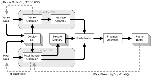
OpenGL Pipeline
OpenGL Pipeline

Display List

Display list is a group of OpenGL commands that have been stored (compiled) for later execution. All data, geometry (vertex) and pixel data, can be stored in a display list. It may improve performance since commands and data are cached in a display list. When OpenGL program runs on the network, you can reduce data transmission over the network by using display list. Since display lists are part of server state and reside on the server machine, the client machine needs to send commands and data only once to server's display list. (See more details in Display List.)
 

Vertex Operation

Each vertex and normal coordinates are transformed by GL_MODELVIEW matrix (from object coordinates to eye coordinates). Also, if lighting is enabled, the lighting calculation per vertex is performed using the transformed vertex and normal data. This lighting calculation updates new color of the vertex. (See more details in Transformation)
 

Primitive Assembly

After vertex operation, the primitives (point, line, and polygon) are transformed once again by projection matrix then clipped by viewing volume clipping planes; from eye coordinates to clip coordinates. After that, perspective division by w occurs and viewport transform is applied in order to map 3D scene to window space coordinates. Last thing to do in Primitive Assembly is culling test if culling is enabled.
 

Pixel Transfer Operation

After the pixels from client's memory are unpacked(read), the data are performed scaling, bias, mapping and clamping. These operations are called Pixel Transfer Operation. The transferred data are either stored in texture memory or rasterized directly to fragments.
 

Texture Memory

Texture images are loaded into texture memory to be applied onto geometric objects.
 

Raterization

Rasterization is the conversion of both geometric and pixel data into fragment. Fragments are a rectangular array containing color, depth, line width, point size and antialiasing calculations (GL_POINT_SMOOTH, GL_LINE_SMOOTH, GL_POLYGON_SMOOTH). If shading mode is GL_FILL, then the interior pixels (area) of polygon will be filled at this stage. Each fragment corresponds to a pixel in the frame buffer.
 

Fragment Operation

It is the last process to convert fragments to pixels onto frame buffer. The first process in this stage is texel generation; A texture element is generated from texture memory and it is applied to the each fragment. Then fog calculations are applied. After that, there are several fragment tests follow in order; Scissor Test ⇒ Alpha Test ⇒ Stencil Test ⇒ Depth Test.
Finally, blending, dithering, logical operation and masking by bitmask are performed and actual pixel data are stored in frame buffer.
 

Feedback

OpenGL can return most of current states and information through glGet*() and glIsEnabled() commands. Further more, you can read a rectangular area of pixel data from frame buffer using glReadPixels(), and get fully transformed vertex data using glRenderMode(GL_FEEDBACK). glCopyPixels() does not return pixel data to the specified system memory, but copy them back to the another frame buffer, for example, from front buffer to back buffer.


◀ PREV 1 NEXT ▶